
Project Story 04 Yumekake-ohashi
Yumekake-ohashi An extradosed bridge that harmoniously integrates structure and design
The Yumekake-ohashi Bridge was constructed over the Kumano River in Gojo City, Nara Prefecture, as part of the Tsujido Bypass Development Project on National Route 168, which connects Hirakata City in Osaka Prefecture and Shingu City in Wakayama Prefecture. The bridge, distinguished by its elegant Y-shaped main tower, received the 2010 Prestressed Concrete Engineering Association Award (Project Category) and the 2018 Japan Society of Civil Engineers Design Award (Encouragement Prize). It was also featured on the cover of a U.S. textbook on bridge engineering.
Features
 Structure
Achieving a slender bridge with high-strength concrete
Structure
Achieving a slender bridge with high-strength concrete
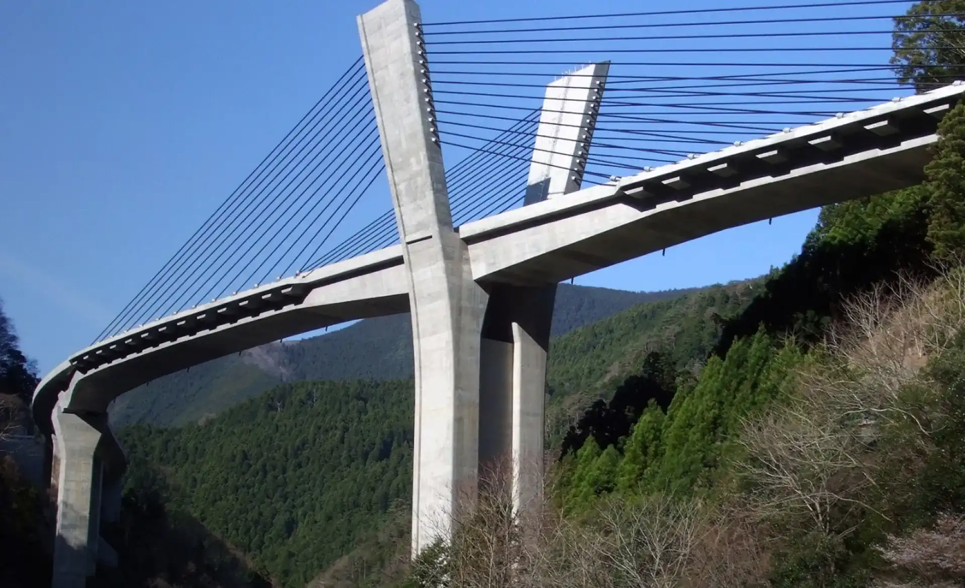
The Yumekake-ohashi Bridge is an extradosed bridge, a type of bridge in which the girder is supported by cables extending from the main tower. Compared to similar cable-stayed bridges, the main tower is lower, and the structure has characteristics more akin to a girder bridge.
The bridge is located in steep mountainous terrain. To reduce environmental impact from terrain modification and to cut costs, compact foundations were adopted. The bridge uses high-strength concrete and high-strength reinforced bars. Notably, the upper structure (girder and main tower) employed high-strength self-compacting concrete with a design strength of 60 N/mm²*, marking the first application of this material in a cable-supported bridge in Japan. The application of these technologies enabled the construction of an even thinner girder than is typical for extradosed bridges, creating a very slender and elegant appearance.
*N/mm² (newtons per square millimeter): A unit indicating how much force can be withstood per unit cross-sectional area. A strength of 60 N/mm² means that a concrete pillar with a 10-cm square cross-section can withstand approximately 60 tons of load.
It is evident that the bridge girder is extremely thin.
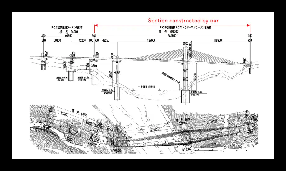
We were responsible for constructing the superstructure of the distinctive extradosed bridge section.
 The Secret of the Y-Shape
"Killing three birds with one stone": Functionality, structure, and aesthetics
The Secret of the Y-Shape
"Killing three birds with one stone": Functionality, structure, and aesthetics
The defining feature of the Yumekake-ohashi Bridge is its Y-shaped main tower. The main tower is the component that suspends the cables supporting the girder, and is a crucial element both structurally and aesthetically.
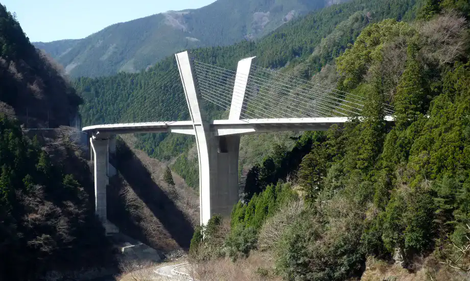
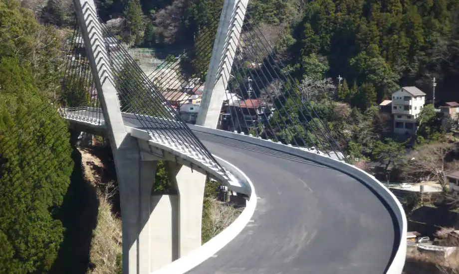
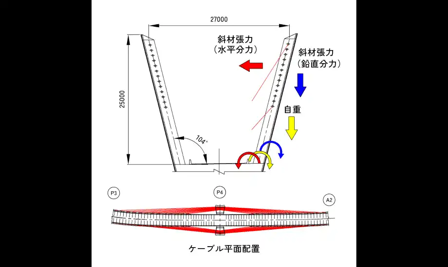
The alignment of Yumekake-ohashi (the road’s layout) is not straight, but gently curved. If cables were extended vertically from the main tower to the curved girder, the outer cables would cross over the roadway and obstruct vehicle traffic. To solve this issue, Yumekake-ohashi features main towers that open outward, ensuring that the cables do not interfere with the roadway even along the curved alignment.
Additionally, because the bridge follows a curve, the cables that suspend the girder exert an inward force (stay cable tension) on the main tower. However, by opening the main tower outward, the self-weight of the tower counteracts and balances this inward force, resulting in a structurally rational design.
The combination of the curved roadway, tall piers, and the outward-opening Y-shaped main towers creates a unique and impressive appearance for Yumekake-ohashi. It is truly a design that achieves functionality, structural rationality, and aesthetics all at once—a true case of "killing three birds with one stone."
 Yumekake-ohashi: Recognized Worldwide
Featured on the covers of international academic journals and American technical books
Yumekake-ohashi: Recognized Worldwide
Featured on the covers of international academic journals and American technical books
The Yumekake-ohashi Bridge received high acclaim for overcoming challenging construction conditions, implementing various measures to preserve the environment and reduce costs by minimizing terrain modification, and for its structurally rational and beautiful design. Domestically, it received the 2010 Prestressed Concrete Engineering Association Award (Project Category) and the 2018 JSCE Design Award (Encouragement Prize).
It was also featured on the cover of the Structural Engineering International journal, with a paper by our employee as the lead author published in the same issue.*
Furthermore, Yumekake-ohashi was also featured on the cover of the book Prestressed Concrete Analysis and Design: Fundamentals by Professor Emeritus Antoine Naaman of the University of Michigan, USA. This textbook provides a thorough and accessible explanation of the fundamentals of prestressed concrete structures, and is widely read by university and graduate students, as well as professionals, in the U.S. and other English-speaking countries. Yumekake-ohashi was featured in this book after Professor Naaman, having seen the cover and read the paper in the Journal of the International Association for Bridge and Structural Engineering, contacted our employee (the paper's lead author) expressing his desire to include it in the revised edition of his textbook. It was a great honor, and we gladly accepted, which led to its inclusion in the textbook.
*Published paper: Hiroshi AKIYAMA, et al.:

Design: Fundamentals
The Bridge Full of InnovationThe Bridge Full of Innovation
Project Overview
-
- Construction Site
-
Oto Town, Gojo City, Nara Prefecture
-
- Project Owner
-
Nara Prefecture
-
- Design
-
Chodai Co., Ltd.
-
- Construction Period
-
March 2007 – March 2010
-
- Project Overview
-
Bridge length: 290.0m
Span lengths: 42.250m + 127.000m + 118.900m
Effective width: 10.510m – 13.552m
Horizontal alignment: R = 200m, A = 110m, L = 58m – 5,000m
Longitudinal gradient: 2.470% – 5.000%
Cross slope: 1.500% – 6.000%
Main girder cross-section: single-cell box girder